
Precision AI Partner

AI Computing Power Demand Is Driving Power
Architecture Transformation

Growth exceeds 8 times
NVIDIA GPU power consumption has surged from 300 W in the Turing era to 2,500 W for Rubin Ultra, representing an increase of more than 8×.

Megawatt (MW) level
The power density of a single AI rack has jumped from the 10 kW class to the 100–400 kW class, and will move toward the megawatt (MW) level in the future.

Large scale deployment
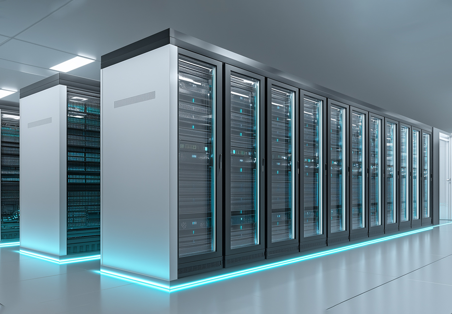
The deployment of large-scale AI clusters has brought unprecedented challenges to traditional power architectures.

Rapid growth
GPU power consumption is growing far faster than Moore’s Law and has become the largest source of power consumption in data centers.
Power Consumption(Watts)
Three Major Pain Points of Traditional
Power Architectures
AI load characteristics expose the critical weaknesses of traditional architectures
 Instantaneous Power Peaks
During parallel computing in GPU clusters, the load can surge from 30% to 180% within milliseconds.
Instantaneous surges can reach tens of kilowatts. Traditional PSUs cannot respond quickly enough, forcing upstreamequipment to be overprovisioned.
 Voltage Sag and
Instability
Sudden load increases cause an immediate drop in busbar voltage, and even small fluctuations can trigger GPU frequency throttling or restarts.
Interruptions in computing power can cause AI inference tasks to fail, resulting in serious business impact and wasted computing resources.
 Power Switching
Gap Risk
Traditional AC UPS switching has delays of tens of milliseconds, which cannot meet 7×24 operation requirements.
For mission-critical AI tasks, any millisecond-level interruption may lead to data loss and service unavailability.
The Revolutionary Advantages of
Supercapacitors
The Perfect Solution for AI Data Centers
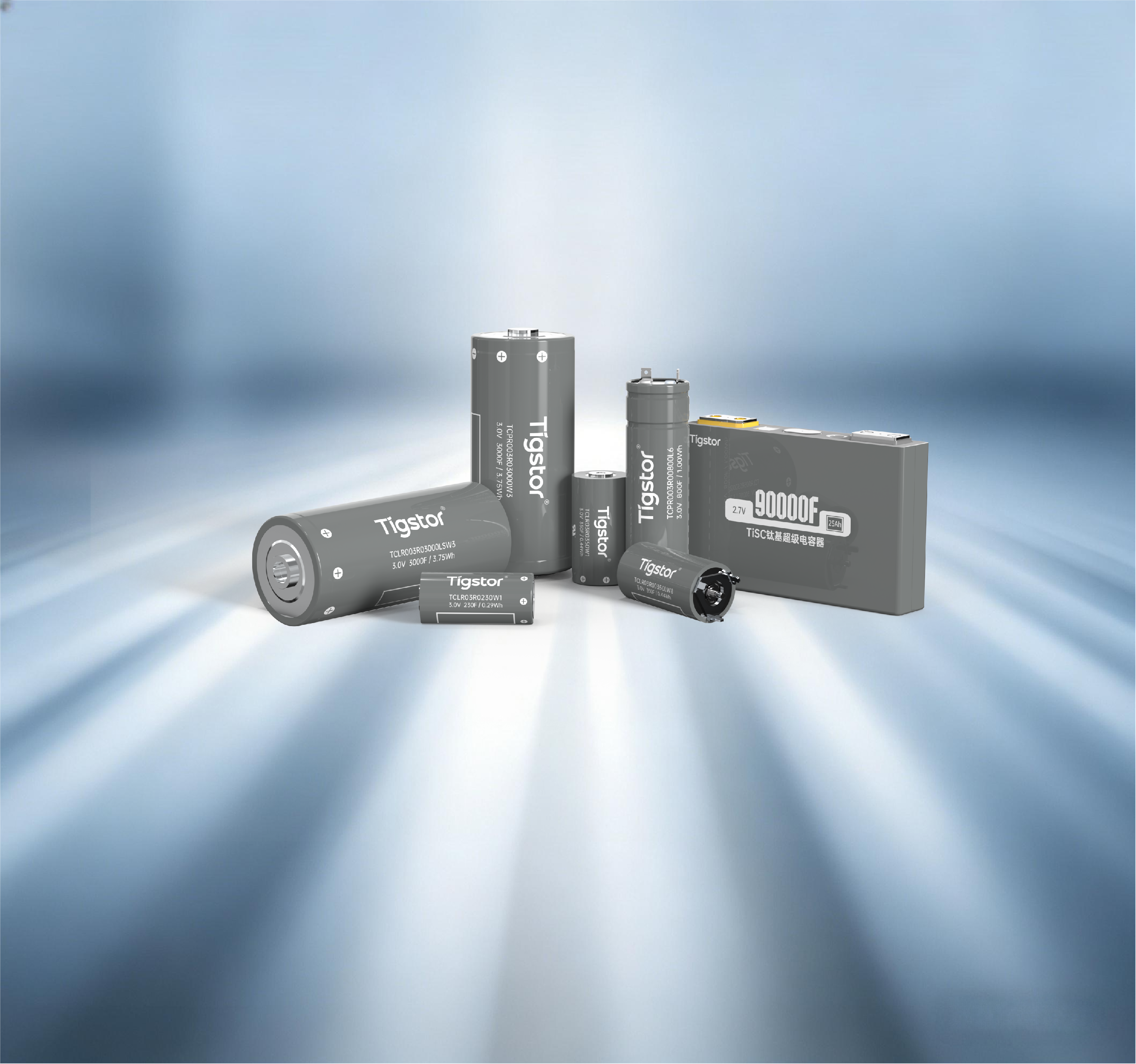
What Is a Capacitor Buffer Unit (CBU)?
A CBU is an energy storage device specifically designed for instantaneous high-power charge/discharge. Unlike conventional batteries, it focuses on “power” rather than “energy,” enabling it to respond to severe AI load fluctuations at millisecond speed.

High Power Density
Its instantaneous charge/discharge capability is dozens of times that of lithium batteries, perfectly absorbing GPU peaks.

Fast Response
Millisecond-level (ms) response time provides immediate compensation for voltage fluctuations.

Ultra-Long Cycle Life
>500,000 cycles with virtually no maintenance throughout the entire lifecycle.
Performance Metrics
Supercapacitor (CBU)
Lithium-Ion Battery (BBU)
Response Speed
Millisecond-level (ms)
Second-level (s)
Power Density
Very High (kW/kg)
Moderate
Cycle Life
>500,000 cycles
~3,000 cycles
Charge/Discharge Rate Capability
>100C
<10C
Core Application
Instantaneous Power Buffering
Long-Duration Backup Power

How CBU Solves the Three Major Pain Points
The Triple Protection Mechanism of the Supercapacitor Buffer Unit

Absorb Instantaneous Power
Peaks
Peaks
Acts as a “power buffer pool,” instantly releasing energy when GPU load surges
Upstream PSUs only need to be designed for average power, with no need for overprovisioning
Recharges quickly when the load drops, preparing for the next peak
Reduced Cost and Space Occupancy

Stabilize Busbar Voltage
Millisecond-level response capability effectively suppresses voltage sag
Provides instantaneous supplementary current to keep voltage within a very small error range
Completely eliminates GPU throttling or restarts caused by unstable voltage
Ensure Continuous and Stable AI Computing Power

Bridge the Power Switching Gap
Seamlessly intervenes when switching to the BBU during utility power interruption
Provides all power during the switching interval, enabling a “zero-power-interruption” transition
The CBU + BBU combination enables truly seamless backup power
Ultimate 7×24 Reliability
The Coordinated Architecture of
BBU and CBU
The Perfect Partnership of Batteries and Supercapacitors: Division of Labor, Each Playing Its Role
Energy
BBU Battery Backup Unit
Composed of lithium-ion batteries, it provides long-duration backup power from minutes to hours. As an “energy reservoir,” it maintains system operation during utility power interruptions.
72 KW
Peak Output (50s)
Minute-Level
Response / Duration
Power
CBU Capacitor Buffer Unit
Composed of supercapacitors, it addresses millisecond-level instantaneous power fluctuations. As a “power buffer pool,” it absorbs GPU load spikes and bridges switching gaps.
156 kW
Peak Output (2s)
Millisecond-Level
Response Speed
Perfect
Partner
Partner
Metrics
BBU w/ Shelf (Lithium Battery)
CBU Flat Type (Supercapacitor)
CBU BBU-like (Supercapacitor)
Dimensions / Weight
2U (88mm) / < 83.3kg
1U (46mm) / < 30kg
2U (88mm) / < 68.9kg
Redundancy Configuration
5+1
1+1
5+1
Peak Output Power
~72.0kW (50sec)
~150kW (2sec)
~156kW (2sec)
Architecture Compatibility
★★★ Native
★☆☆ Adaptation Required
★★★ Fully Compatible
48V Distributed Architecture Inside
the Rack
From Centralized to Distributed: Innovation in Rack-Level Power Architecture
Advantages of Distributed Architecture
48V DC busbar: reduces AC/DC conversion stages and significantly improves end-to-end efficiency.
Seamless switching: CBU provides millisecond-level response, eliminating the switching gap of traditional UPS systems.
Fault isolation: rack-level independent backup power prevents single-point failures from affecting the whole system.
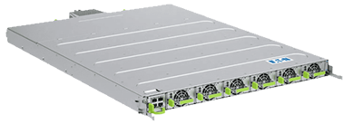
Eaton Open Rack v3 Power Shelf
OCP Standardization (Open Rack v3)
Adopts Open Compute Project standards and supports multi-vendor compatibility (such as Delta and Eaton).
Modular design enables rapid maintenance and capacity expansion.
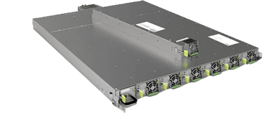
Delta 33kW Power Shelf
Source: OCP, Panasonic, Delta Electronics
Configuration Option
Number of BBUs
Number of CBU Units
CBU Coverage Rate
All-BBU Configuration
18
0
0%
Light Coverage
18
1
51%(75kW)
Medium Coverage
18
2
105%(150kW)
Heavy Coverage
18
3
155%(225kW)

800V High-Voltage Direct Current (HVDC)
Ultimate Architecture
An Energy Efficiency Revolution for Megawatt-Class AI Clusters

Efficiency Leap
When voltage increases from 48 V to 800 V, current is reduced by 16.7×. According to the I² R law, , transmission loss is reduced to 1/280 of the original level, greatly reducing energy waste.
Expand

Space and CostOptimization
When voltage increases from 48 V to 800 V, current is reduced by 16.7×. According to the I² R law, , transmission loss is reduced to 1/280 of the original level, greatly reducing energy waste.
Expand

Future Ready
When voltage increases from 48 V to 800 V, current is reduced by 16.7×. According to the I² R law, , transmission loss is reduced to 1/280 of the original level, greatly reducing energy waste.
Expand
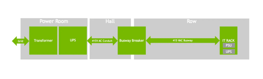
NVIDIA 800V DC Architecture Diagram
Next Generation AI Data Center Rack
Four Stages in the Evolution of Power
Architecture
The Evolution Path from Centralized to Distributed and from Low Voltage to High Voltage

Traditional Centralized UPS Architecture
Multi-stage AC/DC conversion with high losses
Centralized backup power with long switching time
High risk of single-point failure
Applicable to: Traditional Data Centers

Distributed BBU + CBU Architecture
48V DC busbar for improved efficiency
Rack-level backup power with millisecond-level response
Flexible configuration and fault isolation
Applicable to: Current AI Data Centers

Power “Sidecar” Architecture
Physical separation of power and compute cabinets
Optimized space and independent thermal management
Convenient for maintenance and modular upgrades
Applicable to: Ultra-High-Density Clusters

800V High-Voltage Direct Current (HVDC) Architecture
Grid-to-Chip 800V Direct Power Delivery
Current reduced by 16.7× for ultimate efficiency
Supports Megawatt-Class (MW) Racks
Applicable to: Future AI Superclusters
Multi-Level Deployment of Supercapacitor
Applications
Comprehensive Coverage from Chip-Level Protection to Data Center-Level Regulation
Deployed near the motherboard
or OAM module
or OAM module
Eliminate Voltage Spikes
Protect Expensive GPU Chips

SERVER
LEVEL
Deployed inside the 48V power
shelf (CBU)
shelf (CBU)
Stabilize Busbar Voltage
Absorb Millisecond-Level Load Fluctuations

POWER SHELF LEVEL
Deployed on the side (Sidecar)
or at the bottom of the rack
or at the bottom of the rack
Peak Shaving and Valley Filling
Reduce Peak Rack Power Demand

RACK LEVEL
Centralized Containerized Systems or
Large-Scale Energy Storage Arrays
Large-Scale Energy Storage Arrays
Frequency Regulation
Improve Overall Power Quality

DATA CENTER LEVEL
Technical Challenges and Solution Directions
Key Technical Barriers to the Next-Generation Power Architecture
High Power Density BBU
Development
Development
CHALLENGE:
How to improve energy density while maintaining extremely high-rate discharge capability and ensuring thermal stability.
DIRECTION
Structured integrated design using high-power, high-safety cells such as TiSC titanium-based hybrid capacitors.

Future Outlook and Opportunities
Evolution Roadmap and Industry Opportunities for AI Power Architectures

Short Term (1–3 YEARS)
48V + CBU Becomes Widely Adopted
With the deployment of high-power-consumption chips such as Blackwell, 48V distributed architecture will rapidly replace 12V. CBU will become a standard configuration to solve instantaneous power peak issues and reduce TCO.

Mid Term (3–5 YEARS)
Liquid Cooling & Sidecar Become Mainstream
When single-rack power exceeds 100 kW, air cooling will completely exit the core computing area. The Power Sidecar model physically decouples power from computing, optimizing thermal management and space.

Long Term (5+ YEARS)
800V HVDC Reshapes Data Centers
For megawatt-class (MW) clusters, 800V HVDC will become the ultimate architecture. It will achieve ultimate Grid-to-Chip efficiency and reduce transmission losses to the minimum.
For Operators
Plan power capacity and liquid cooling infrastructure in advance; adopt modular power architectures and reserve room for future upgrades to 800V.
For Vendors
Accelerate the development of high-voltage (800V+) power devices; develop solutions for “lithium battery + supercapacitor” hybrid energy storage systems (Hybrid ESS).